
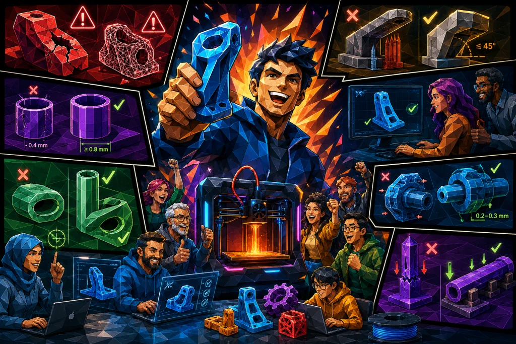
How to ensure strong parts and avoid production stops by validating your design digitally.
Many people work under the misconception that a 3D printer works exactly like a coffee machine. The expectation is often that you press a button, and then the machine delivers a perfect result every time. However, the reality is different. Although the technology has become more accessible, the process remains a craft where the digital design must respect the physical limitations of the machine.
At our facility, we daily validate files from both engineers and designers. We frequently encounter the same technical errors. These errors determine whether you receive a strong, functional component or if the print fails mid-production. Here we review the technical solutions so your file becomes ready for production the first time.
What does it mean if a file is “non-manifold”?
The term “non-manifold” often appears as an error message in slicer software. Although it sounds technical, it covers a simple logic. Consider your 3D model as a bucket. If you pour water into the digital model, the water must stay inside. If the model has holes, or the surfaces do not meet correctly, the water will run out.
The requirement for a watertight model
A 3D file must be “watertight.” This means that all edges must meet precisely, and there must be no holes in the surface. The printer cannot interpret geometry where surfaces are missing or where the model intersects itself. Another typical problem is “zero-thickness walls.” This occurs when a wall is drawn as a single 2D line without thickness. In the physical world, all objects must have a volume.
You can solve these problems by using the “Inspect” or “Repair” functions in your CAD software. Alternatively, there are tools like Meshmixer that automatically identify and close holes before you upload the file for a 3D print service.
Wall thickness and strength in 3D print
A 3D print is built from lines of melted plastic. The smallest building block in this process is determined by the nozzle diameter, which is typically 0.4 mm. A classic mistake is designing walls that are thinner than this diameter, such as 0.2 mm. Slicer software will in many cases ignore these walls, as they cannot physically be produced.
The rule of nozzle diameter
To ensure stability, you should design your walls as a multiple of the nozzle width. A good rule of thumb is to design walls with a thickness of at least 0.8 mm to 0.9 mm. This corresponds to two paths of plastic.
This thickness creates an outer and an inner shell, which provides significantly better strength than a single, thin wall. Although modern slicing engines like Arachne try to compensate for varying line widths, you achieve the most predictable result by maintaining a minimum thickness of approximately twice the nozzle width.
Handling overhangs and support structures
3D printers cannot print in thin air. Each layer requires a foundation of hardened plastic from the layer below. If your model has overhangs that exceed 45 degrees, gravity will cause the warm plastic to sag. In these cases, we must add support material. This material costs extra in INR and often leaves a rougher surface that requires post-processing.
Use chamfers instead of fillets
You can often design your way out of the need for support. Use chamfers instead of fillets on the underside of your overhangs. A 45-degree chamfer builds gradually outward and can be printed perfectly without support. A fillet, on the other hand, starts horizontally in the air, which will fail without support.
Compensation for “Elephant’s Foot”
The very first layers placed against the build plate are often squeezed slightly out to the sides due to weight and heat. This phenomenon is called “Elephant’s foot” and can ruin your tolerances if the part needs to fit into a hole. You counteract this by adding a small chamfer of 0.5 mm along the bottom of your model. This gives the material room to flow out without exceeding the intended dimensions.
Tilt the model 10 degrees
In some cases, a simple rotation can save the print. If you tilt the entire model just 10 degrees, you change the angle of your overhangs. This can make an otherwise impossible overhang self-supporting and thus take the action of removing the need for support structures entirely.
Why horizontal holes lose their shape
If you place a cylindrical hole horizontally in your model, you will often find that it does not turn out perfectly round. This is because the printer builds the hole layer-by-layer. The top of the hole becomes a bridging project where the plastic can sag slightly, making the hole oval or flat at the top.
The teardrop shape as a solution
The most effective solution is to rotate the model so the hole stands vertically like a chimney. In this orientation, the printer draws the circle precisely via its X and Y axes.
If the design requires the hole to lie horizontally, you should consider using the “Teardrop” shape. Here, you design the hole like a droplet where the top tapers at a 45-degree angle. This removes the flat ceiling that requires support and ensures the hole maintains its functional diameter, so an axle or bolt still fits through.
Resolution and visible seams
When you export your file to STL format, your round curves are converted into many small, flat triangles. If the resolution is too low, your circles will look like hexagons on the finished 3D print. If the resolution is too high, the file becomes unnecessarily heavy to process without providing a visible visual improvement.
Placement of Z-seam
A 3D printer must start and stop at a point on each layer. This creates a small, visible line along the object, known as a “Z-seam.” On a completely smooth cylinder, this line will be obvious. You can improve the aesthetics by designing a small groove or a sharp edge in your model where the slicer can hide this seam so it does not disturb the surface.
Orientation determines strength
Orientation is about more than just fitting on the build plate. It is crucial for the physical strength of the part. An FDM 3D print is strong across the layers but has a weakness in the bonding between layers along the Z-axis.
Imagine a long, thin rod. If it is printed standing upright, it will break easily as the layers are simply stacked on top of each other. However, if the rod lies down during the printing process, the plastic paths run along the rod through its entire length. This makes it significantly stronger. Therefore, always analyze which direction your part will be loaded in and orient it so the layers work with the force.
Correct tolerances for assemblies
It causes great frustration to have two parts that need to be assembled but do not fit together. This is often due to a lack of understanding regarding material shrinkage and geometric limitations.
Material shrinkage
Plastic shrinks as it cools. The extent depends on the material. PLA is very dimensionally stable and typically shrinks less than 1 percent, while more technical materials like Nylon can shrink up to 3 percent. If you need precise dimensions, you must factor this shrinkage into your CAD model.
Corners and dog-bone fillets
Imagine you have to draw an internal corner with a thick marker. You will never be able to draw a sharp 90-degree corner because the stroke will always curve. A 3D printer nozzle works the same way. A square peg will therefore not fit into a square hole because the hole’s corners are rounded by the nozzle’s radius. The solution is to create “Dog-bone” fillets. These are small round cutouts in the internal corners that provide space for the counterpart’s sharp edge.
Checklist for production-ready files
Use this overview to validate your data before sending your file to production.
| Error type | Consequence | Solution |
| Non-manifold | Holes in the model, print fails. | Use “Repair” function in CAD or Meshmixer. |
| Thin walls | Wall is missing or breaks. | Min. 0.8 mm to 0.9 mm thickness. |
| Large overhangs | Poor surface or collapse. | Use max 45 degrees or add chamfers. |
| Horizontal holes | Hole is oval. | Use “Teardrop” shape or print vertically. |
| Incorrect tolerance | Parts do not assemble. | Add 0.2 mm to 0.3 mm air between parts. |
FAQ: 3D print design
Here you will find answers to the most common questions regarding the optimization of files for 3D print. If you need deeper technical insight, we recommend reading the full guide above.
How thick should the walls be on a 3D print?
You should design walls with a minimum thickness of 0.8 mm to 0.9 mm, which corresponds to two paths of plastic. Walls thinner than the nozzle diameter (typically 0.4 mm) often cannot be printed. A thickness of at least twice the nozzle width ensures stability and strength in the part, so it does not break during use or production.
What does it mean that a 3D file is non-manifold?
Non-manifold means that your 3D model has holes in the surface or edges that do not meet correctly, so it is not “watertight.” A 3D printer cannot print a model with holes in the geometry. You must repair the file in your CAD program or use software like Meshmixer to close the holes before the file can be produced flawlessly.
When is it necessary to use support in 3D print?
Support is necessary if your model has overhangs that exceed an angle of 45 degrees relative to the build plate. Without support, gravity will cause the warm plastic to sag. You can often avoid support by using chamfers instead of fillets or by rotating the model so the angle is changed to below the limit.
How much tolerance should there be between assembled 3D printed parts?
You should include a clearance of 0.2 mm to 0.3 mm between parts that need to be assembled. Plastic shrinks during cooling, and the printer’s nozzle cannot create perfectly sharp internal corners. Without this air, the parts will not be able to click together. Remember also to take the material’s specific shrinkage percentage into account in your design.
How do I make my 3D print stronger through design?
You increase the strength significantly by orienting the part so the layers lie lengthwise with the expected load. FDM 3D print is weakest between the layers (Z-axis). A rod printed lying down is therefore much stronger than one printed standing up. Think about the force impact and the part’s function before you place and orient the object on the digital build plate.
Why do horizontal holes in 3D print become oval?
Horizontal holes often lose their shape at the top because the printer struggles to bridge the void layer by layer. To avoid this, you can design the hole as a “Teardrop,” where the top tapers at 45 degrees. Alternatively, you should print the part vertically so the hole stands like a chimney, which ensures a perfect circle.
Optimize the process from design to finished part
3D print is a discipline where physics and design meet. By following these guidelines, you ensure a better result, but also a lower price in INR and faster delivery, as we avoid manual corrections and stoppages.
If you are in doubt about the design, you should change one variable at a time. Do not adjust material, wall thickness, and orientation simultaneously when testing a prototype. This makes it impossible to identify what actually solved the problem.
When your file is optimized, you can upload it directly to our price calculator. The system analyzes the geometry and gives you an offer immediately, so we can take action and start your production.